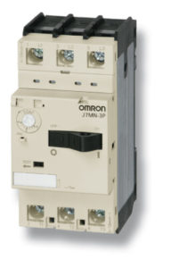
J7MN
- Номинальный рабочий ток для моделей с нажимным переключателем: номинал от 0,16 А до 32 А; с поворотным переключателем: от 0,16 до 32 А; от 26 до 63 А; от 63 до 100 А.
- Коммутационная способность для всех версий: от 15 кА до 100 кА
- Компания Omron предлагает версии четырех различных размеров
- Автоматы защиты двигателя могут крепиться винтами на основание или защелкиваться на DIN-рейке
- Защита от соприкосновения с токоведущими частями
Характеристики и информация для заказа
| Rated current in A | Suitable for motors 3 ~ 400 V kW | Current setting range | Short-circuit breaking capacity at 3 ~ 400 V kA | Size in mm (H × W × D) | Order code | |
| Thermal overload release A | Instantaneous short-circuit release A | |||||
| 0.16 | — | 0.10-0.16 | 2.1 | 100 | 98 × 45 × 75 | J7MN-3P-E16 |
| 0.25 | 0.06 | 0.16-0.25 | 3.3 | 100 | J7MN-3P-E25 | |
| 0.4 | 0.09 | 0.25-0.4 | 5.2 | 100 | J7MN-3P-E4 | |
| 0.63 | 0.18 | 0.4-0.63 | 8.2 | 100 | J7MN-3P-E63 | |
| 1 | 0.25 | 0.63-1 | 13 | 100 | J7MN-3P-1 | |
| 1.6 | 0.55 | 1-1.6 | 20.8 | 100 | J7MN-3P-1E6 | |
| 2.5 | 0.75 | 1.6-2.5 | 32.5 | 100 | J7MN-3P-2E5 | |
| 4 | 1.5 | 2.5-4 | 52 | 100 | J7MN-3P-4 | |
| 6 | 2.2 | 4-6 | 78 | 100 | J7MN-3P-6 | |
| 8 | 3 | 5-8 | 104 | 100 | J7MN-3P-8 | |
| 10 | 4 | 6-10 | 130 | 50 | J7MN-3P-10 | |
| 13 | 5.5 | 9-13 | 169 | 50 | J7MN-3P-13 | |
| 17 | 7.5 | 11-17 | 221 | 20 | J7MN-3P-17 | |
| 22 | 7.5 | 14-22 | 286 | 15 | J7MN-3P-22 | |
| 26 | 11 | 18-26 | 338 | 15 | J7MN-3P-26 | |
| 32 | 15 | 22-32 | 416 | 15 | J7MN-3P-32 | |
| 0.16 | — | 0.10-0.16 | 2.1 | 100 | 98 × 45 × 100 | J7MN-3R-E16 |
| 0.25 | 0.06 | 0.16-0.25 | 3.3 | 100 | J7MN-3R-E25 | |
| 0.4 | 0.09 | 0.25-0.4 | 5.2 | 100 | J7MN-3R-E4 | |
| 0.63 | 0.18 | 0.4-0.63 | 8.2 | 100 | J7MN-3R-E63 | |
| 1 | 0.25 | 0.63-1 | 13 | 100 | J7MN-3R-1 | |
| 1.6 | 0.55 | 1-1.6 | 20.8 | 100 | J7MN-3R-1E6 | |
| 2.5 | 0.75 | 1.6-2.5 | 32.5 | 100 | J7MN-3R-2E5 | |
| 4 | 1.5 | 2.5-4 | 52 | 100 | J7MN-3R-4 | |
| 6 | 2.2 | 4-6 | 78 | 100 | J7MN-3R-6 | |
| 8 | 3 | 5-8 | 104 | 100 | J7MN-3R-8 | |
| 10 | 4 | 6-10 | 130 | 100 | J7MN-3R-10 | |
| 13 | 5.5 | 9-13 | 169 | 100 | J7MN-3R-13 | |
| 17 | 7.5 | 11-17 | 221 | 50 | J7MN-3R-17 | |
| 22 | 7.5 | 14-22 | 286 | 50 | J7MN-3R-22 | |
| 26 | 11 | 18-26 | 338 | 50 | J7MN-3R-26 | |
| 32 | 15 | 22-32 | 416 | 50 | J7MN-3R-32 | |
| 26 | 12.5 | 18-26 | 338 | 50 | 140 × 55 × 144 | J7MN-6R-26 |
| 32 | 15 | 22-32 | 416 | 50 | J7MN-6R-32 | |
| 40 | 18.5 | 28-40 | 520 | 50 | J7MN-6R-40 | |
| 50 | 22 | 34-50 | 650 | 50 | J7MN-6R-50 | |
| 63 | 30 | 45-63 | 819 | 50 | J7MN-6R-63 | |
| 63 | 30 | 45-63 | 819 | 50 | 165 × 70 × 171 | J7MN-9R-63 |
| 75 | 37 | 55-75 | 975 | 50 | J7MN-9R-75 | |
| 90 | 45 | 70-90 | 1170 | 50 | J7MN-9R-90 | |
| 100 | — | 80-100 | 1300 | 50 | J7MN-9R-100 | |
Accessories
| Description | Version | For circuit breaker | Order code | |
| Transverse auxiliary contact block | ||||
| Contact block | 1 NO + 1 NC | All | J77MN-11F | |
| 2NO | J77MN-20F | |||
| 2NC | J77MN-02F | |||
| Auxiliary contact block for left hand side mounting (max. 2 pc. per circuit breaker) | ||||
| Contact block (9 mm) | 1 NO + 1 NC | All | J77MN-11S | |
| 2NO | J77MN-20S | |||
| 2NC | J77MN-02S | |||
| Signalling switch for left hand side mounting (max. 1 pc. per circuit breaker) | ||||
| Signalling switch (18 mm) | 1 NO + 1 NC any tripping condition | J7MN-3P/-3R | J77MN-TA-11S | |
| J7MN-6R/-9R | J77MN-TB-11S | |||
| 1 NO + 1 NC short circuit tripping condition | All | J77MN-T-11S | ||
| Undervoltage releases for right hand side mounting (max 1 pc. per circuit breaker) | ||||
| AC 50 Hz | AC 60 Hz | |||
| Trips the circuit breaker when the voltage is interrupted. Prevents the motor from being restarted accidentally when the voltage is restored, suitable for EMERGENCY STOP according to VDE 0113 | 24 V | 28 V | All | J77MN-U-24 |
| 110-127 V | 120 V | J77MN-U-110 | ||
| 220-230 V | 240-260 V | J77MN-U-230 | ||
| 240 V | 277 V | J77MN-U-240 | ||
| 380-400 V | 440-460 V | J77MN-U-400 | ||
| 415-440 V | 460-480 V | J77MN-U-415 | ||
| Shunt releases for right hand side mounting (max 1 pc. per circuit breaker) | ||||
| AC 50 Hz | AC 60 Hz | |||
| Trips the circuit breaker when the release coil is energized | 24 V | 28 V | All | J77MN-S-24 |
| 110-127 V | 120 V | J77MN-S-110 | ||
| 220-230 V | 240-260 V | J77MN-S-230 | ||
| 240 V | 277 V | J77MN-S-240 | ||
| 380-400 V | 440-460 V | J77MN-S-400 | ||
| 415-440 V | 460-480 V | J77MN-S-415 | ||
| Terminal block | ||||
| Terminal block | Up to 600 V according to UL 489 not for transverse auxiliary contact block | J7MN-3R | J77MN-TB32 | |
| J7MN-9R | J77MN-TB100 | |||
Insulated 3-Phase Busbar System IP20
| Description | Connection type | Version | For Units (MPCB) | Order code |
| 3-phase busbars; modular spacing = 45 mm | Spade | for 2 units | J7MN-3P; J7MN-3R | J77MN-CPM-3-45-2S |
| for 3 units | J77MN-CPM-3-45-3S | |||
| for 4 units | J77MN-CPM-3-45-4S | |||
| for 5 units | J77MN-CPM-3-45-5S | |||
| Line side terminal 3-pole, connection from above;
conductor cross-section solid or stranded 6-25 mm² with end sleeve 4-16 mm² |
Spade | acc. IEC/EN 60947-1, 60947-2, 60947-4-1 and VDE 0660 | J7MN-3P; J7MN-3R | J77MN-BTC-63-SE |
| Line side terminal 3-pole,
connection from above;
conductor cross-section solid or stranded 6-25 mm² with end sleeve 4-16 mm² |
Spade | up to 600 V acc. UL 489 | J7MN-3P; J7MN-3R | J77MN-BTC-63-SEV |
| Shrouds for unused terminals on busbar system | Spade | J7MN-3P; J7MN-3R | J77MN-TA-63S |
Specifications
| Type | J7MN-3P | J7MN-3R | J7MN-6R | J7MN-9R | |
| Number of poles | 3 | 3 | 3 | 3 | |
| Max. rated current Inmax (= max. rated operational current Ie) | A | 32 | 32 | 63 | 100 |
| Permissible ambient temperature | Storage/transport | -50 to 80°C | |||
| Operation | -20 to 60°C | ||||
| Rated operational voltage Ue | V | 690 | |||
| Rated frequency | Hz | 50/60 | |||
| Rated insulation voltage Ui | V | 690 | |||
| Rated impulse withstand voltage Uimp | kV | 6 | |||
| Utilization category | IEC 60 947-2 (circuit breaker) | A | |||
| IEC 60 947-4-1 (motor starter) | AC-3 | ||||
| Class | According to IEC 60 947-4-1 | 10 | |||
| Degree of protection | According to IEC 60 529 | IP20 | IP20 | IP20 | IP20 |
| Phase failure sensitivity | According to IEC 60 947-4-1 | Yes | |||
| Explosion protection | According to EC Directive 94191EC | Yes | |||
| Isolator characteristics | According to IEC 60 947-3 | Yes | |||
| Main and EM. STOP switch characteristics | According to IEC 60 204-1 (VDE113) | Yes | |||
| Safe isolation between main and auxiliary circuits According to DIN VDE 0106 Part 101 | Up to 400 V + 10% | Yes | |||
| Up to 415 V + 5% | Yes | ||||
| Mechanical endurance | Operating cycles | 100,000 | 100,000 | 50,000 | 50,000 |
| Electrical endurance | 100,000 | 100,000 | 25,000 | 25,000 | |
| Max. operating frequency per hour (motor starts) | 1/h | 25 | 25 | 25 | 25 |

