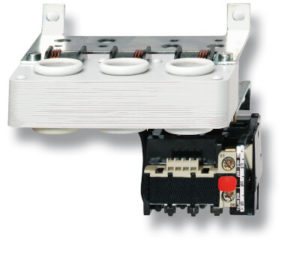
J7TKN
- Серия реле перегрузки охватывает диапазон токов от 0,24 A до 220 A
- Защита от соприкосновения с токоведущими частями
Характеристики и информация для заказа
| Applicable contactors | Setting range | Size in mm (H × W × D)
(incl. standard J7KN[A] contactor |
Order code | |
| D.O.L. (A) | Star-delta (A) | |||
| J7KNA-09…, J7KNA-12… | 0.12 to 0.18 | — | 95 × 48.5 × 77 | J7TKN-A-E18 |
| 0.18 to 0.27 | — | J7TKN-A-E27 | ||
| 0.27 to 0.4 | — | J7TKN-A-E4 | ||
| 0.4 to 0.6 | — | J7TKN-A-E6 | ||
| 0.6 to 0.9 | — | J7TKN-A-E9 | ||
| 0.8 to 1.2 | — | J7TKN-A-1E2 | ||
| 1.2 to 1.8 | — | J7TKN-A-1E8 | ||
| 1.8 to 2.7 | — | J7TKN-A-2E7 | ||
| 2.7 to 4 | — | J7TKN-A-4 | ||
| 4 to 6 | 7 to 10.5 | J7TKN-A-6 | ||
| 6 to 9 | 10.5 to 15.5 | J7TKN-A-9 | ||
| 8 to 11 | 14 to 19 | J7TKN-A-11 | ||
| 10 to 14 | 18 to 24 | J7TKN-A-14 | ||
| J7KN-10D… to J7KN-40… | 0.12 to 0.18 | — | 126.5 × 45 × 70 (J7KN-10D to J7KN-22D); 141.5 × 45 × 87.5 (J7KN-24 to J7KN-40) |
J7TKN-B-E18 |
| 0.18 to 0.27 | — | J7TKN-B-E27 | ||
| 0.27 to 0.4 | — | J7TKN-B-E4 | ||
| 0.4 to 0.6 | — | J7TKN-B-E6 | ||
| 0.6 to 0.9 | — | J7TKN-B-E9 | ||
| 0.8 to 1.2 | — | J7TKN-B-1E2 | ||
| 1.2 to 1.8 | — | J7TKN-B-1E8 | ||
| 1.8 to 2.7 | — | J7TKN-B-2E7 | ||
| 2.7 to 4 | — | J7TKN-B-4 | ||
| 4 to 6 | 7 to 10.5 | J7TKN-B-6 | ||
| 6 to 9 | 10.5 to 15.5 | J7TKN-B-9 | ||
| 8 to 11 | 14 to 19 | J7TKN-B-11 | ||
| 10 to 14 | 18 to 24 | J7TKN-B-14 | ||
| 13 to 18 | 23 to 31 | J7TKN-B-18 | ||
| 17 to 24 | 30 to 41 | J7TKN-B-24 | ||
| 23 to 32 | 40 to 55 | J7TKN-B-32 | ||
| J7KN-24… to J7KN-40… | 28 to 42 | 48 to 73 | 136 × 67 × 96.5 | J7TKN-C-42 |
| J7KN-50… to J7KN-74… | 40 to 52 | 70 to 90 | 180 × 69 × 108 | J7TKN-D-52 |
| 52 to 65 | 90 to 112 | J7TKN-D-65 | ||
| 60 to 74 | 104 to 128 | J7TKN-D-74 | ||
| J7KN-90… to J7KN-115… | 60 to 90 | 104 to 156 | 260 × 107 × 120 | J7TKN-E-90 |
| 80 to 120 | 140 to 207 | J7TKN-E-120 | ||
| J7KN-151… to J7KN-176… | 120 to 180 | 208 to 312 | 290 × 110 × 162 | J7TKN-F-180 |
| J7KN-210… to J7KN-316… | 144 to 216 | 250 to 374 | 362 × 145 × 208 | J7TKN-G-216 |
| 216 to 320 | 374 to 554 | J7TKN-G-320 | ||
| J7KN-450… to J7KN-860… | 240 to 360 | 416 to 623 | 372 × 1246 × 1225 (J7KN-450)
395 × 1246 × 1225 (J7KN-550) 487 × 1280 × 1291 (J7KN-700) 540 × 1280 × 1291 (J7KN-860) |
J7TKN-H-360 |
| 360 to 540 | 623 to 935 | J7TKN-H-540 | ||
| 540 to 800 | 935 to 1385 | J7TKN-H-800 | ||
Accessories
Sets for single mounting
| For overload relays | Cable cross-section to clamp (mm 2 ) | Order code | ||
| Solid or stranded | Flexible | Flexible with multi-core cable | ||
| J7TKN-AB | 0.75 to 6 | 0.75 to 4 | 0.5 to 4 | J74TK-M-AB |
| J7TKN-B | 0.75 to 6 | 0.75 to 4 | 0.5 to 4 | J74TK-SM |
Busbar sets for thermal overload relays
| For overload relays | For motor contactors | Order code |
| J7TKN-H-360/540 | J7KN-450/550 | J74TK-SU-550 |
| J7TKN-H-540/800 | J7KN-700/860 | J74TK-SU-860 |
Specifications
| Type | J7TKN-A | J7TKN-B | J7TKN-C | J7TKN-D | J7TKN-E | J7TKN-F | J7TKN-G | J7TKN-H | |
| Rated insulation voltage Ui | 690 VAC | 750 VAC | 1000 VAC | ||||||
| Permissible ambient temperature | Operation | -25 to 60°C | -25 to 55°C | ||||||
| Storage | -50 to 70°C | -40 to 70°C | |||||||
| Trip class according to IEC 947-4-1 | 10 A | 20 A | 10 A | ||||||
| Cable cross-section Main connector | Solid or stranded mm2 | 0.75 to 6
0.75 to 2.5 |
0.75 to 6 | 0.75 to 10 | 4 to 35 | Without terminals, suitable for bushing one connector 70 mm² (stranded) per phase | Busbar 18×4 Screw M8 | Busbar 25×6 Screw M10 | See accessories |
| Flexible mm2 | 0.75 to 4
0.5 to 2.5 |
1 to 4 | 0.75 to 6 | 6 to 25 | |||||
| Flexible with multi-core cable end mm2 | 0.5 to 2.5
0.5 to 1.5 |
0.75 to 4 | 0.75 to 6 | 4 to 25 | |||||
| Cables per clamp | Number | 1 + 1 | 2 | 2 | 1 | — | 1 | 1 | 1 |
| Auxiliary connector | Solid mm2 | 0.75 to 2.5 | 1 to 2.5 | ||||||
| Flexible mm2 | 0.5 to 2.5 | 1 to 2.5 | |||||||
| Flexible with multi-core cable end mm2 | 0.5 to 1.5 | 1 to 2.5 | |||||||
| Cables per clamp | Number | 2 | |||||||
| Cables per clamp | |||||||||
| Rated insulation voltage Ui | Same potential | 690 VAC | 500 VAC | ||||||
| Different potential | 440 VAC | 250 VAC | 440 VAC | 500 VAC | |||||
| Rated operational current Ie Utilization category AC15 | 24 V | 5 A | 3 A | 4 A | 5 A | 3 A | 4 A | ||
| 230 V | 3 A | 2 A | 2.5 A | 2.5 A | 3 A | 2 A | 2.5 A | ||
| 400 V | 2 A | 1 A | 1.5 A | 1.5 A | 2 A | 1 A | 1.5 A | ||
| 690 V | 0.6 A | 0.5 A | 0.6 A | 0.5 A | 0.6 A | ||||
| Rated operational current Ie
Utilization category DC13 |
24 V | 1.2 A | 1 A | 1.2 A | |||||
| 110 V | 0.15 A | ||||||||
| 220 V | 0.1 A | ||||||||
| Short circuit protection (without welding 1 kA) | Highest fuse rating gL (gG) | 6 A | 4 A | 6 A | 4 A | 6 A | |||
| Setting range | to 23 A | All | 28 to 42 A | 52 to 65 A | All | — | — | — | |
| Power loss per current path (max.) | Minimum setting value | 1.1 W | 1.1 W | 1.3 W | 2.9 W | 1.1 W | — | — | — |
| Maximum setting value | 2.3 W | 2.3 W | 3.3 W | 4.5 W | 2.5 W | — | — | — | |

