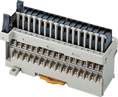
G70D
- Тонкая клеммная колодка 135 × 40 мм (Ш × Г)
- Независимые контакты и перемычки обеспечивают простое общее подключение
- Для подключения линии питания можно установить дополнительную клеммную колодку
- Можно использовать вилочные обжимные клеммы M3.5 (с максимальной шириной клеммы 6,2 мм)
- Рычажный механизм позволяет легко устанавливать и снимать реле без использования инструментов
- Доступны модели реле и силовые реле с МОП-транзистором
- Оснащены индикаторами
- Возможность объединения с терминалом ввода/вывода DRT2-OD32ML для подключения к DeviceNet или терминалом разъема SRT2-VOD16ML для подключения к CompoBus/S
- Установка либо на DIN-рейку, либо при помощи винтов
Характеристики и информация для заказа
Relay Terminals
| Classification | Points | Internal I/O common | Rated voltage | Order code |
| Relay outputs | 16 points (SPST-NO × 16) | NPN (+common) | 24 V DC | G70D-VSOC16 |
| Power MOSFET relay outputs | G70D-VFOM16 |
Note:
These are all non-standard model and require a special order. Contact your OMRON representative for details on availability.
Accessories (Order Separately)
Cables for I/O Relay Terminals XW2Z-R
| Type | Order code | ||
| Cable with Loose Wire and Crimp Terminals | XW2Z-RY⬜C | ||
| Cable with Loose Wires | XW2Z-RA⬜C | ||
| Cable with connectors | Fujitsu connectors | 1:1 | XW2Z-R⬜C |
| 1:2 | XW2Z-RI⬜C-⬜ | ||
| XW2Z-RO⬜C-⬜ | |||
| 1:3 | XW2Z-R⬜C-⬜-⬜ | ||
| MIL connectors | 1:1 | XW2Z-RI⬜C | |
| XW2Z-RO⬜C | |||
| 1:2 | XW2Z-RI⬜-⬜-D⬜ | ||
| XW2Z-RM⬜-⬜-D⬜ | |||
| XW2Z-RO⬜-⬜-D1 | |||
Relay Terminal
| Applicable Output Relay Terminals | Order code |
| G70D-VSOC16 | G70D-ET |
| G70D-VFOM16 |
Short Bar
| Applicable Output Relay Terminals | Order code |
| G70D-VSOC16 | G6D-4-SB |
| G70D-VFOM16 |
Replacement Relays
| Applicable Output Relay Terminals | Rated voltage | Order code |
| G70D-VSOC16 | 24 V DC | G6D-1A-ASI-AP DC24 |
| G70D-VFOM16 | G3DZ-2R6PL DC24 |
Accessories for DIN Track Mounting
Refer to your OMRON website for details on the PFP-⬜.
Specifications
Relay Specifications
The following specifications apply to G6D Relays mounted in a G70D Relay Terminal and not the G6D Relay itself.
Coil Ratings (per G6D Relay)
| Rated voltage | 24 VDC |
| Rated current | 10.5 mA |
| Coil resistance | 2,880 Ω |
| Must-operate voltage | 70% max. of rated voltage |
| Must release voltage | 10% min. of rated voltage |
| Max. voltage | 130% of rated voltage |
| Power consumption | Approx. 200 mW |
Note:
1. The must-operate voltage is 75% or less of the rated voltage if the relay is mounted upside down.
2. Rated current and coil resistance were measured at a coil temperature of 23° C with a tolerance of ±10%.
3. Operating characteristics were measured at a coil temperature of 23° C.
4. The maximum allowable voltage is the maximum value of the allowable voltage range for the relay coil operating power supply. There is no continuous allowance.
5. The rated current includes the terminal’s LED current.
Contact Ratings (per G6D Relay)
| Load | Resistive load (cosφ = 1) | |
| Rated load | 3 A at 250 VAC, 3 A at 30 VDC | |
| Rated carry current | 5 A | |
| Max. switching voltage | 250 VAC, 30 VDC | |
| Max. switching current | 5 A | |
| Max. switching capacity (reference value) | 1,250 VA, 150 W | |
| Min. permissible load (reference value) | 5 VDC, 1 mA | |
| Endurance | Electrical | 100,000 operations min. (under and at the rated load at 1,800 operations/h) |
| Mechanical | 20,000,000 operations min. (at 18,000 operations/h) |
Power MOSFET Relay Specifications
The following values apply to G3DZ Relays mounted in a G70D Output Block and not the G3DZ Relay itself.
Input (per G3DZ Power MOSFET Relay)
| Rated voltage | 24 VDC | |
| Operating voltage | 19.2 to 28.8 VDC | |
| Voltage level | Must-operate | 19.2 VDC max. |
| Must release | 1 VDC min. | |
| Input impedance | 4 kΩ±20% | |
| Rated current | 8.2 mA±20% | |
Note:
The rated current includes the current consumption of the operation indicator.
Output (per G3DZ Power MOSFET Relay)
| Load voltage | 3 to 264 VAC, 3 to 125 VDC |
| Load current | 100 μA to 0.3 A |
| Inrush current | 6 A (10 ms) |
Characteristics
| Item | G70D-VSOC16 | G70D-VFOM16 | |
| Relay outputs | Power MOSFET Relay outputs | ||
| Contact configuration | 16 points (SPST-NO × 16) | ||
| Contact structure | Single | – | |
| Contact resistance | 100 mW max. | – | |
| Isolation method | – | Photocoupler | |
| Must-operate time | 10 ms max. | 10 ms max. | |
| Release time | 10 ms max. | 15 ms max. | |
| Output ON-resistance | – | 2.4 W max. | |
| Open-circuit leakage current | – | 10 mA max. (at 125 V DC) | |
| Max. switching frequency | Mechanical: 18,000 operations/h
Rated load: 1,800 operations/h |
– | |
| Insulation resistance | 100 MW min. (at 500 V DC) | ||
| Dielectric strength | 2,000 V AC for 1 min between coil and contact | 2,000 V AC for 1 min between input and output terminals | |
| Noise immunity | Vibration resistance | Destruction: 10 to 55 to 10 Hz, 0.5-mm amplitude (1.0-mm double)
Malfunction: 10 to 55 to 10 Hz, 0.375-mm amplitude (0.75-mm double) |
|
| Shock resistance | Destruction: 300 m/s2, Malfunction: 100 m/s2 | ||
| Operating voltage range | 24 V DC +10%/–15% | ||
| Current consumption | Approx. 170 mA at 24 V DC | Approx. 125 mA at 24 V DC | |
| Cable length | Between block and controller: 5 m max. (reference value for AWG28)
Between block and external device: Dependent on load |
||
| LED color | Operation indicator: orange | ||
| Coil surge absorber | Diode (600 V, 1 A) | ||
| Ambient temperature | Operating: -25 to 55°C (with no icing or condensation) | ||
| Ambient humidity | Operating: 45% to 85% | ||
| Mounting strength | No damage when 49 N pull load was applied for 1 s in all directions (except for 9.8 N in direction of rail) | ||
| Terminal strength | Tightening torque: 0.78 to 118 N·m
Pull strength: 49 N for 1 min |
||
| Weight | Approx. 280 g | ||
Note:
These values are initial values.