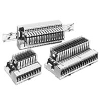
G7TC
- Компактный размер: 182 (Ш) 2,85 (Г) 2,68 (В) мм (ширина 8-точечного выходного блока 102 мм).
- Подключается к ПЛК через разъем и требует только защелкивания.
- Встроенная цепь с защитой от скачков напряжения.
- Мгновенное распознавание состояния включения/выключения с помощью светодиодных индикаторов срабатывания.
- Твердотельное реле ввода/вывода G3TA может быть установлено вместо G7T.
- Легко устанавливается на DIN-рейку.
- Одобрено UL, CSA (кроме G7TC-OC16-1).
Характеристики и информация для заказа
I/O Relay Terminal
| I/O classification | I/O points | Internal I/O common | Rated voltage | Order code |
| Input | 16 | NPN (- common) | 12 VDC | G7TC-ID16 |
| 24 VDC | ||||
| 100 (110) VDC | ||||
| 100/(110) VAC | G7TC-IA16 | |||
| 200/(220) VAC | ||||
| Output | 16 | NPN (+ common) | 12 VDC | G7TC-OC16 |
| 24 VDC | ||||
| PNP (– common) | 12 VDC | G7TC-OC16-1 | ||
| 24 VDC | ||||
| 8 | NPN (+ common) | 12 VDC | G7TC-OC08 | |
| 24 VDC |
Note:
1. When ordering, add the rated coil voltage to the model number. Example: G7TC-ID1 24 VDC
2. When the G7TC is used with an AC rated voltage, three rated currents can be used. If a coil voltage of 110 or 220 VAC is used, 50 Hz cannot be used.
Accessories (Order Separately)
Cable for I/O Relay Terminals XW2Z-R
| Type | Order code | ||
| Cable with Loose Wire and Crimp Terminals | XW2Z-RY⬜C | ||
| Cable with Loose Wires | XW2Z-RA⬜C | ||
| Cable with connectors | Fujitsu connectors | (1:1) | XW2Z-R⬜C |
| (1:2) | XW2Z-RI⬜C-⬜ | ||
| XW2Z-RO⬜C-⬜ | |||
| (1:3) | XW2Z-R⬜C-⬜-⬜ | ||
| MIL connectors | (1:1) | XW2Z-RI⬜C | |
| XW2Z-RO⬜C | |||
| (1:2) | XW2Z-RI⬜-⬜-D⬜ | ||
| XW2Z-RM⬜-⬜-D⬜ | |||
| XW2Z-RO⬜-⬜-D1 | |||
Note:
Refer to Connecting Cables for details.
Short Bar
| Item | Order code |
| Short Bar | G78-04 |
Output Short-Circuit Module
| Item | Order code |
| Output Short-Circuit Module | G77-S |
Socket
| Item | Order code |
| Socket | P7TF-05 |
Indicator Module (With Surge Suppressing Function)
| Applicable relay coil voltage | Remarks | Order code | |
| For AC relay | 100 (110) V AC | Varistor surge suppression | P70A |
| 200 (220) V AC | |||
| For DC relay | 12/24 V DC | Diode surge suppression | P70D |
Note:
1. Order the indicator module suitable for the relay coil voltage.
2. The indicator module for DC relays can be used with a 12-V or 24 V DC power supply.
Accessories for DIN Track Mounting
| Name | Minimum order (quantity) | Order code | |
| DIN Tracks | 1 m | 1 | PFP-100N |
| 0.5 m | PFP-50N | ||
| End Plate | 10 | PFP-M | |
| Spacer | PFP-S | ||
Specifications
Coil Ratings (Common to Input/Output per Relay)
| Item | Rated current (mA) | Coil resistance (Ω) | Must operate | Must release | Maximum voltage | Power consumption | |||
| Rated voltage (V) | 50 Hz | 60 Hz | of rated voltage | per Relay | per 16 Relays | ||||
| AC | 100/(110) | 8.2/– | 7/7.7 | 8,700 | 80% max. | 30% min. | 105% | 0.7 VA | 11 VA |
| 200/(220) | 4.1/– | 3.5/3.85 | 33,300 | ||||||
| DC | 12 | 42 | 290 | 80% max. | 10% min. | 105% | 0.5 W | 8 W | |
| 24 | 21 | 1,150 | |||||||
| 100/110 | 5 | 20,000 | |||||||
Note:
1. The rated current and coil resistance are measured at a coil temperature of 23°C with a tolerance of 15%/-20% for AC rated current and ±15% for coil resistance.
2. The operating characteristics are measured at a coil temperature of 23°C.
3. The value for maximum voltage is the maximum value within the allowable voltage fluctuation range for the relay coil’s operating power supply. Continuous operation at this voltage is not within product specifications.
4. Approx. 4 mA flows into each LED indicator. To calculate the power supply capacity, add the current value of each LED indicator.
5. When the G7TC is used with an AC rated voltage, three rated currents can be used. If a coil voltage of 110 or 220 VAC is used, 50 Hz cannot be used.
Contact Ratings (G7T I/O Relay)
| Classification | For input | For output | ||
| Item | Resistive load (cosϕ=1) | Inductive load
(cosϕ=0.4 L/R=7 ms) |
Resistive load (cosϕ=1) | Inductive load
(cosϕ=0.4 L/R=7 ms) |
| Rated load | 1 A at 24 VDC | 0.5 A at 24 VDC | 2 A at 220 VAC
5 A at 24 VDC |
1 A at 220 VAC
2 A at 24 VDC |
| Rated carry current | 1 A | 5 A | ||
| Max. switching voltage | 250 VAC, 125 VDC | |||
| Max. switching current | 1 A | 0.5 A | 5 A | 2 A |
| Error rate (reference value) | 100 μA at 1 V | 10 mA at 5 V | ||
| Electrical endurance | 10,000,000 operations (at 10 mA)
50,000 operations (at 1 A) |
2,500,000 operations (at 10 mA)
20,000 operations (at 1 A) |
1,000,000 operations (under rated load) | |
| Mechanical endurance | 50,000,000 operations | |||
Characteristics
| Item | G7TC-IA16
(Input, AC coil) |
G7TC-ID16
(Input, DC coil) |
G7TC-ID16
G7TC-OC16 (–1) (output, DC coil) |
G7TC-OC08
(output, DC coil) |
|
| Contact form | SPST-NO × 16 | SPST-NO × 8 | |||
| Contact mechanism | Bifurcated crossbar contact | Single contact | |||
| Contact material | Au cladding + Ag | AgInSn | |||
| Contact resistance | 50 mΩ max. | ||||
| Must Operate time | 15 ms max. | ||||
| Release time | 15 ms max. | ||||
| Max. switching frequency | Mechanical limit | 18,000 operations/h | |||
| At rated load | 1,800 operations/h | ||||
| Insulation resistance | 100 MΩ (at 500 VDC) | ||||
| Dielectric strength | Between coil and contact | 2,000 VAC, 50/60 Hz for 1 minute | |||
| Between same polarity contacts | 1,000 VAC, 50/60 Hz for 1 minute | ||||
| Between paired connectors | 250 VAC, 50/60 Hz for 1 minute | ||||
| Vibration resistance | 10 to 55 to 10 Hz with 0.5-mm single amplitude (1.0-mm double amplitude) | ||||
| Shock resistance | 200 m/s2 | ||||
| Noise immunity | Noise level: 1.5 kV; pulse width: 100 ns to 1 μs | ||||
| Rated voltage between positive and negative terminal blocks | Rated voltage of controller’s (PLC or other) input circuit | 12 VDC ±5%
24 VDC ±5% |
|||
| Rated current between positive and negative terminal blocks | Input circuit current of controller (PLC or other) × number of ON points | 12 VDC: 46 mA × number of ON points
24 VDC: 25 mA × number of ON points |
|||
| Cable length | To controller | 5 m max. (reference value) | |||
| To I/O devices | 50 m max. (reference value, for 2-mm2 CVV cable) | Dependent on load | |||
| Ambient operating temperature | 0 to 55°C | ||||
| Ambient operating humidity | 35% to 85% (with no icing or condensation)C | ||||
| Tightening torque for external connections | 0.78 to 1.18 N·m | ||||
| Tensile strength | No damage when a tensile force of 49 N is applied in each direction.
In the direction of the track, the tensile strength is 9.8 N min. |
||||
| I/O terminal tightening torque | Tightening strength: 0.98 N·m; Tensile strength 49 N per minute | ||||
| LED color | Red | Green | |||
| Case color | Transparent red | Transparent green | Transparent green | ||
| Coil surge absorber | Varistor | Diode (1 A, 1,000 V) | |||
| Weight | Approx. 640 g | Approx. 630 g | Approx. 670 g | Approx. 350 g | |
Note:
The above values are initial values.
Approved Standards
The rated values for safety standard certification are not the same as individually defined performance values. Always check the specifications before use.
Standard G7TC I/O Relay Terminal, except for the G7TC-OC16-1 and the G7TC-OC08, have met UL and CSA standards (UL file no. E95399; CSA file no. LR35535).
UL standard certification (File No. E95399)
| Model | Standard number | Category | Listed/Recognized | Contact ratings |
| G7TC-ID16
G7TC-IA16 |
UL508 | NRAQ2 | Recognized | Terminal block side: 250 VAC max./point
Connector side: 10 mA/point, 24 VDC |
| G7TC-OC16 | UL508 | NRAQ2 | Recognized | Terminal block side:
Inductive load: 10 A, 250 VAC Resistive load: 10 A, 30 VDC Rated horsepower: 1/2 HP, 240 VAC |
CSA Standard (File No. LR35535)
| Model | Standard number | Class number | Contact ratings |
| G7TC-ID16 | CSA C22.2
No.14 |
3211 04 | 6 to 240 VAC
6 to 125 VDC |
| G7TC-IA16 | |||
| G7TC-OC16 |