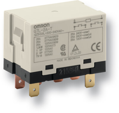
G7L
- Типы контактов: нормально разомкнутые SPST или DPST
- Быстрая установка в монтажную колодку, монтаж на печатную плату или винтовые клеммы
- Номинальный ток нагрузки 20, 25 или 30 A
- Невосприимчивы к кратковременному падению напряжения
- Широкая область применения с катушками на 100 или 200 В
Характеристики и информация для заказа
| Contact form |
Mounting |
Terminals |
Order code |
Common Coil Voltages |
| PCB |
DIN-rail front connecting socket |
DIN Rail adaptor |
Flange (screw) |
E-bracket mounting |
PCB |
Quick-connect |
Screw |
DC |
AC |
| SPST-NO |
no |
yes |
yes |
no |
yes |
no |
yes |
no |
G7L-1A-T___ |
24 |
100/120, 200/240 |
| DPST-NO |
G7L-2A-T___ |
12, 24 |
24, 100/120, 200/240 |
| SPST-NO |
no |
no |
yes |
no |
G7L-1A-TUB___ |
− |
100/120, 200/240 |
| DPST-NO |
G7L-2A-TUB___ |
24 |
24, 200/240 |
| no |
yes |
G7L-2A-BUB___ |
− |
200/240 |
| yes |
no |
yes |
no |
G7L-2A-P___ |
24 |
− |
Accessories
| For type |
Order code |
| DIN-rail front connecting socket |
DIN Rail adaptor |
E-Bracket mounting |
Coverplate electric shock protection |
| G7L Screw terminal type |
− |
P7LF-D |
R99-07G7L |
P7LF-C |
| G7L Quick Connect type |
P7LF-06 |
P7LF-D |
R99-07G7L |
− |
Specifications
Coil Ratings
| Rated voltage |
Rated current |
Coil resistance |
Must operate voltage |
Must release voltage |
Max. voltage |
Power consumption (approx.) |
| AC (~) |
12 V |
142 mA |
− |
75% max.of rated voltage |
15% min. of rated voltage |
110% of rated voltage |
1.7 to 2.5 VA (60 Hz) |
| 24 V |
71 mA |
− |
| 50 V |
34 mA |
− |
| 100 to 120 V |
17.0 to 20.4 mA |
− |
74 V |
18 V |
132 V |
| 200 to 240 V |
8.5 to 10.2 mA |
− |
150 V |
36 V |
264 V |
| DC (=) |
6 V |
317 mA |
18.9 Ohm |
75% max. of rated voltage |
15% min. of rated voltage |
110% of rated voltage |
1.9 W |
| 12 V |
158 mA |
75 Ohm |
| 24 V |
79 mA |
303 Ohm |
| 48 V |
40 mA |
1220 Ohm |
| 100 V |
19 mA |
5260 Ohm |
Note 1. The rated current and coil resistance are measured at a coil temperature of 23°C with tolerances of ±15%/20% for AC rated current and ±15% for DC coil resistance.
2. Performance characteristic data are measured at a coil temperature of 23°C.
3. ~ indicates AC and = indicates DC (IEC417 publications).
Contact Ratings
| Model |
G7L-1A-TJ/G7L-1A-BJ |
G7L-2A-TJ/G7L-2A-BJ |
G7L-1A-P/G7L-2A-P |
| Resistive load (cos φ = 1) |
Inductive load (cos φ = 0.4) |
Resistive load (cos φ = 1) |
Inductive load (cos φ = 4.4) |
Resistive load (cos φ = 1) |
Inductive load (cos φ = 4.4) |
| Rated load |
30 A, 220 VAC (~) |
25 A, 220 VAX (~) |
25 A, 220 VAC (~) |
20 A, 220 VAC (~) |
| Rated carry current |
30 A |
25 A |
20 A |
| Max. switching voltage |
250 VAC (~) |
| Max. switching current |
30 A |
25 A |
20 A |
| Max. switching power |
6,600 VAC (~) |
5,500 VAC (~) |
5,500 VAC (~) |
4,400 VAC (~) |
| Failure rate (reference value) |
100 mA, 5 VDC (=) |
Документация